Building a Robot Disguised as a Christmas Present


Russell Wong | 2021-01-05

As the holidays were approaching, I came up with a strange idea for a robotics project. Twas the season of giving, and this year I wanted to give my friends and family a gift that would be unique and completely unexpected. So I decided to surprise them by constructing a present box that is actually a robot in disguise!

In this blog post, I will explain how I designed and built a walking Christmas present robot. The code, CAD and resources for this project can be found below. It may look like a Christmas present from the outside, but this box-shaped bot can extend its legs to quickly take on its quadrupedal form.

I'm using an Arduino Mega board as the brain of the robot, which runs the code to listen to Bluetooth commands and actuate the servo motors. The robot parts are 3D printed from PLA plastic. The robot's walking motions can be controlled wirelessly over Bluetooth, and provides a unique approach for delivering holiday gifts to family and friends. Check out their reactions in the video below:

Mechanical Design

The CAD model for the robot can be found here. The model is provided in STEP format so that it can be opened in any CAD software.

The main components of the robot are the four legs to propel the robot's motion, four walls to complete the box-shaped exterior, and a base/main body which supports all other components and electronics. The overall design is inspired by several open source hexapod robotics projects, though of course this robot has only four legs instead of six, and is specifically modeled to have a box-like appearance.

The base plate of the robot is supported by four caster wheels. This ensures that the robot will be statically stable regardless of its gait. For example, I want the robot's walking pattern to appear more dynamic by lifting two of its legs at a time when taking a step. The caster wheels would provide support to prevent the robot from toppling over during this motion, without the need for a complex controller and without restricting the robot from translating or rotating in any direction. By design, the wheels would also be concealed by the walls of the gift box, so this would not take away from any of the aesthetics either.

A second plate provides a surface to mount the internal electronics. The two plates are spaced apart to allow clearance for the servo motors. The plates are separated by four modified I-beams, which have an additional outward-facing flat surface to support the walls of the gift box.

Each robot leg has 3 degrees of freedom. The leg consists of three servos, a thigh component and a calf component. Two servos are mounted near the base using custom brackets at 90 degree angles to each other. This effectively creates a compact hip joint that rotates the entire leg with respect to the base. The third servo pivots the calf with respect to the thigh, similar to a knee joint. The thigh component is designed much smaller than the calf so that there is no interference when the legs retract. The outer surfaces of the calves are shaped to match the corners of the robot's box-shaped profile.

In order to look like a convincing gift box, four stationary walls are fixed to the modified I-beams, and can later be covered with gift wrapping. The profiles of the legs are designed to align with the walls of the box to show minimal gap when retracted. There are several cuts in the walls as well so that the legs have enough range to pivot without colliding with the walls while walking. The interior of the wall features a shelving platform which can be used to hold a small gift inside the robot.

Altogether, the mechanical design allows the machine to function as a walking quadruped robot, with a box-like appearance to take the form of a Christmas present when the legs are retracted.

Electrical Design

Below is a schematic illustrating the electrical design of the robot.

I'm using a 3S 5000 mAh LiPo battery to power the system, in order to supply sufficient current to the servo motors under full load. It's a bit overkill for this project, but it's the only battery I have that can handle the current draw, so I figure I'll use it rather than purchasing a new one. Since the rest of the electronics operate at 5V, I'm using a DC-DC converter to step down the battery's 11.1V to the required 5V.

The Arduino Mega runs the code to listen for Bluetooth commands and subsequently actuate the servos. According to Arduino's documentation you should be able to control the 12 servos with the Servo library using a single timer board such as the Arduino UNO, but I've opted to use the Mega to give myself more digital pins to work with, i.e. to support Bluetooth as well as reserving pins 0 and 1 for the Serial monitor when debugging. I'm using MG995 servo motors to actuate the robot's legs, and an HC-05 Bluetooth module to send commands wirelessly from my phone.

(Note: the HC-05 Bluetooth module will only work with Android devices. A different module may be required to communicate with an iOS device.)

A capacitor is placed in parallel with the servos to smooth out any current peaks. 1000-2000 µF seems to be more than enough for my purposes. A voltage divider is used at the RX pin of the HC-05 module to shift the 5V output from the Arduino Mega to the appropriate 3.3V logic level.

Servo Calibration

Standard servos have a range of 0-180 degrees; however this is only approximate, and each individual servo may have variability. For this project, I am only working with each servo over a 90 degree range and the full 180 degrees is not required. Therefore, I'll be calibrating each servo to be accurate in the range of 45-135 degrees. Working within this range will be sufficient for the full range of motion for each robot leg. This will also avoid accidentally writing angles beyond the servo's 0-180 degree range, which would be a high current state and could cause damages.

The servo_pwm_write script available in the GitHub repository for this project can be used for calibration. First, attach a round servo horn to the servo you want to calibrate, and wire it to the Arduino Mega board. Connect the servo's power wire to 5V, ground wire to GND, and the signal wire to the digital pin number defined here. The program allows the user to write a PWM signal to the servo specified in microseconds to change the servo's angular position.


    #include <Servo.h>
    
    const int SERVO_PIN = 30;
    Servo servo;
    
    void setup() {
      Serial.begin(9600);
      servo.attach(SERVO_PIN);
      servo.write(90);
    }
    
    void loop() {
      while (Serial.available() > 0) {
        int us = Serial.parseInt();
        if (us > 2400 || us < 600) {
          Serial.println("Error: out of bounds");
        } else {
          servo.writeMicroseconds(us);
          Serial.print("Wrote "); Serial.print(us); Serial.println(" us");
        }
        do {
          Serial.read();
        }  while (Serial.available() > 0);
        delay(15);
      }
    }
                

After uploading the code to the Arduino and running the script, the servo should turn to approximately the 90 degree position. I can then open the Serial monitor and enter an integer in microseconds to write to the servo:

This process is used to visually observe which values of microseconds would pivot the servo to the 45, 90 and 135 degree positions. From there, the pulse range for the servo (i.e., the microsecond values corresponding to 0 and 180 degrees) can be calculated.

For example, suppose the pulse values for 45, 90 and 135 degrees are 1000, 1500 and 2000 microseconds respectively. In other words, incrementing by 45 degress equates to an additional 500 microsecond increase. This means the pulse range would theoretically be 500-2500 microseconds for the full 0-180 degree range.

Note that this method only works because I'm using the servo over a limited 45-135 degree range; in the above example, it wouldn't be a good idea to actually write 500 or 2500 microseconds to the servo because this could put the servo in a high current state.

The calibration procedure can be repeated for all 12 servos. Once completed, the pulse ranges are recorded here to be used later in the main executable code.


    int PULSE_RANGES[NUM_SERVOS][2] = {
        {550, 2550},
        {325, 2425},
        {500, 2500},
        {550, 2550},
        {580, 2460},
        {460, 2460},
        {500, 2500},
        {530, 2530},
        {425, 2425},
        {590, 2510},
        {625, 2525},
        {465, 2405}
    };
                

Software

All code used in this project can be found in the GitHub repository.

A set of Matlab scripts are used to simulate the walking motion of the robot. The main script can be found here. First, a model of the robot is created in simulation using the Robotics System Toolbox. The create_robot_body function takes in a series of parameters used to define the dimensions of the robot, such as the robot's radius, relative transformations between the leg joints (i.e., servos) and initial joint angles. Most of these parameters were measured from the CAD model, although these can be changed to simulate motion of differently sized quadruped robots.

Next, a path is created for the foot to follow. The path is generated from one of four stride types as defined below:


    StrideTypes.MOVE_FORWARD
    StrideTypes.MOVE_BACKWARD
    StrideTypes.ROTATE_CW
    StrideTypes.ROTATE_CCW
                

The create_foot_path function returns a path represented by lists of discrete points. These points are defined in rectangular coordinates (x, y, z) for stride types MOVE_FORWARD and MOVE_BACKWARD, and in polar coordinates (θ, ρ, z) for stride types ROTATE_CW and ROTATE_CCW.


    % Create relative paths
    [lift_path, drag_path] = create_foot_path(STRIDE_TYPE, FULL_STRIDE_LENGTH, FULL_STRIDE_ARC_LENGTH,
                                              ROBOT_RADIUS, STEP_HEIGHT, FULL_STRIDE_TIME, TIME_DELTA);
                

The returned path is divided into two parts, a lift_path and a drag_path. The lift_path consists of relative coordinates that move the foot along a parabolic curve in the z direction, to lift it off the ground and take a step. The drag_path contains the relative coordinates required to drag the foot along the ground, which returns the foot back to its original position and creates the necessary friction to move the robot. Opposite pairs of feet on the robot alternate between the lift and drag paths, which creates the overall walking motion.

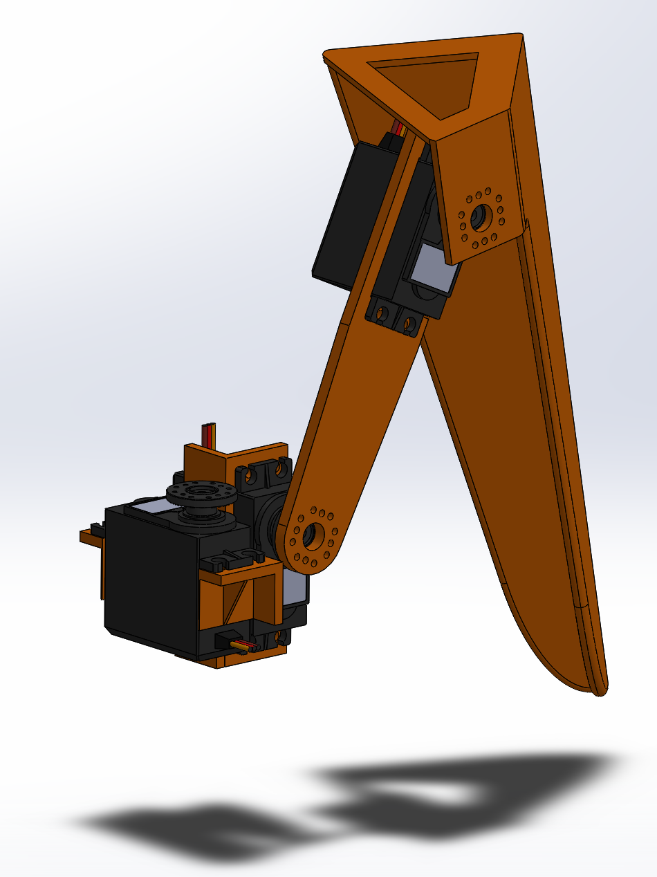
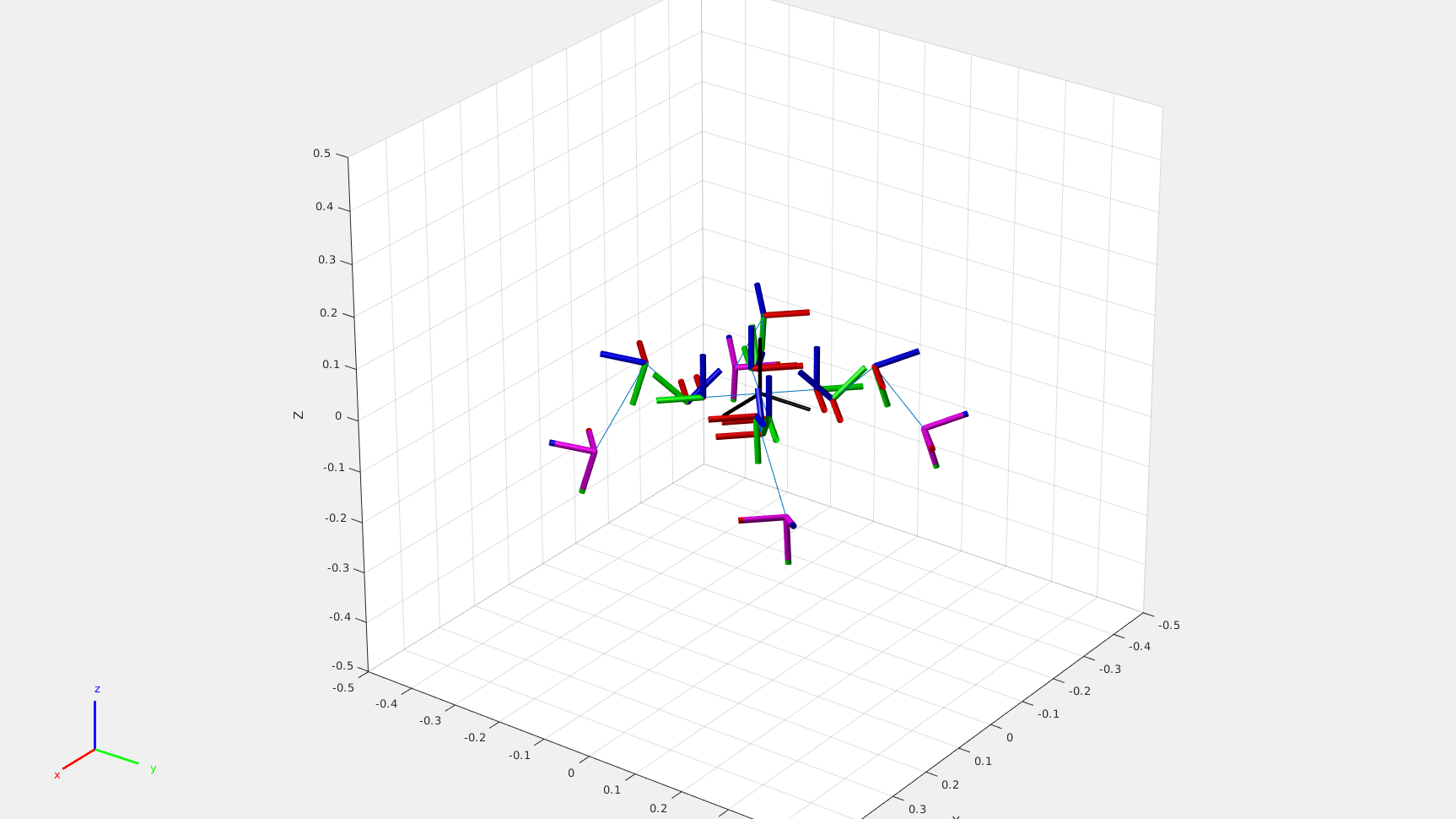
After calculating the ideal path for each foot to follow, the script applies an inverse kinematics solver at each point in the path. Inverse kinematics is the process of computing the joint angles in some chain of rigid bodies required to place some end effector at a desired position and/ or orientation. In this case, the chain of bodies is the robot leg, the joints are located at the servo motors, and the end effector is the foot. The code snippet which runs the inverse kinematics solver is shown below.


    % Inverse Kinematics
    q0 = homeConfiguration(robot);
    num_dof = length(q0);
    num_timesteps_per_path = size(lift_path, 1);
    qs = zeros(NUM_CYCLES*2*num_timesteps_per_path, num_dof);
    ik = robotics.InverseKinematics('RigidBodyTree', robot);
    weights = [0, 0, 0, 1, 1, 1];
    for i = 1:NUM_CYCLES
        % First half-cycle: lift legs 1 and 3
        foot1_start_pos = get_pos(robot, q0, 'foot1');
        foot2_start_pos = get_pos(robot, q0, 'foot2');
        foot3_start_pos = get_pos(robot, q0, 'foot3');
        foot4_start_pos = get_pos(robot, q0, 'foot4');
        q_init = q0; 
        for j = 1:num_timesteps_per_path
            % Define destination points for each foot
            if STRIDE_TYPE == StrideTypes.MOVE_FORWARD || STRIDE_TYPE == StrideTypes.MOVE_BACKWARD
                % Rectangular coordinates
                foot1_dest_pos = lift_path(j,:) + foot1_start_pos;
                foot2_dest_pos = drag_path(j,:) + foot2_start_pos;
                foot3_dest_pos = lift_path(j,:) + foot3_start_pos;
                foot4_dest_pos = drag_path(j,:) + foot4_start_pos;
            else
                % Cylindrical coordinates
                foot1_dest_pos = pol_plus_cart(lift_path(j,:), foot1_start_pos);
                foot2_dest_pos = pol_plus_cart(drag_path(j,:), foot2_start_pos);
                foot3_dest_pos = pol_plus_cart(lift_path(j,:), foot3_start_pos);
                foot4_dest_pos = pol_plus_cart(drag_path(j,:), foot4_start_pos);
            end
    
            % Run IK for each foot
            q_sol1 = ik('foot1', trvec2tform(foot1_dest_pos), weights, q_init); % indices 1:3 are relevant to foot1
            q_sol2 = ik('foot2', trvec2tform(foot2_dest_pos), weights, q_init); % indices 4:6 are relevant to foot2
            q_sol3 = ik('foot3', trvec2tform(foot3_dest_pos), weights, q_init); % indices 7:9 are relevant to foot3
            q_sol4 = ik('foot4', trvec2tform(foot4_dest_pos), weights, q_init); % indices 10:12 are relevant to foot4
    
            % Add solution to the qs solution matrix
            q_sol = [q_sol1(1:3), q_sol2(4:6), q_sol3(7:9), q_sol4(10:12)];
            idx = 2*num_timesteps_per_path*(i-1)+j;
            qs(idx,:) = q_sol;
            q_init = q_sol;
        end
    
        % Second half-cycle: lift legs 2 and 4
        foot1_start_pos = get_pos(robot, q_init, 'foot1');
        foot2_start_pos = get_pos(robot, q_init, 'foot2');
        foot3_start_pos = get_pos(robot, q_init, 'foot3');
        foot4_start_pos = get_pos(robot, q_init, 'foot4');
        for j = 1:num_timesteps_per_path
            % Define destination points for each foot
            if STRIDE_TYPE == StrideTypes.MOVE_FORWARD || STRIDE_TYPE == StrideTypes.MOVE_BACKWARD
                % Rectangular coordinates
                foot1_dest_pos = drag_path(j,:) + foot1_start_pos;
                foot2_dest_pos = lift_path(j,:) + foot2_start_pos;
                foot3_dest_pos = drag_path(j,:) + foot3_start_pos;
                foot4_dest_pos = lift_path(j,:) + foot4_start_pos;
            else
                % Cylindrical coordinates
                foot1_dest_pos = pol_plus_cart(drag_path(j,:), foot1_start_pos);
                foot2_dest_pos = pol_plus_cart(lift_path(j,:), foot2_start_pos);
                foot3_dest_pos = pol_plus_cart(drag_path(j,:), foot3_start_pos);
                foot4_dest_pos = pol_plus_cart(lift_path(j,:), foot4_start_pos);
            end
    
            % Run IK for each foot
            q_sol1 = ik('foot1', trvec2tform(foot1_dest_pos), weights, q_init); % indices 1:3 are relevant to foot1
            q_sol2 = ik('foot2', trvec2tform(foot2_dest_pos), weights, q_init); % indices 4:6 are relevant to foot2
            q_sol3 = ik('foot3', trvec2tform(foot3_dest_pos), weights, q_init); % indices 7:9 are relevant to foot3
            q_sol4 = ik('foot4', trvec2tform(foot4_dest_pos), weights, q_init); % indices 10:12 are relevant to foot4
    
            % Add solution to the qs solution matrix
            q_sol = [q_sol1(1:3), q_sol2(4:6), q_sol3(7:9), q_sol4(10:12)];
            idx = 2*num_timesteps_per_path*(i-1)+j+num_timesteps_per_path;
            qs(idx,:) = q_sol;
            q_init = q_sol;
        end
    end
                

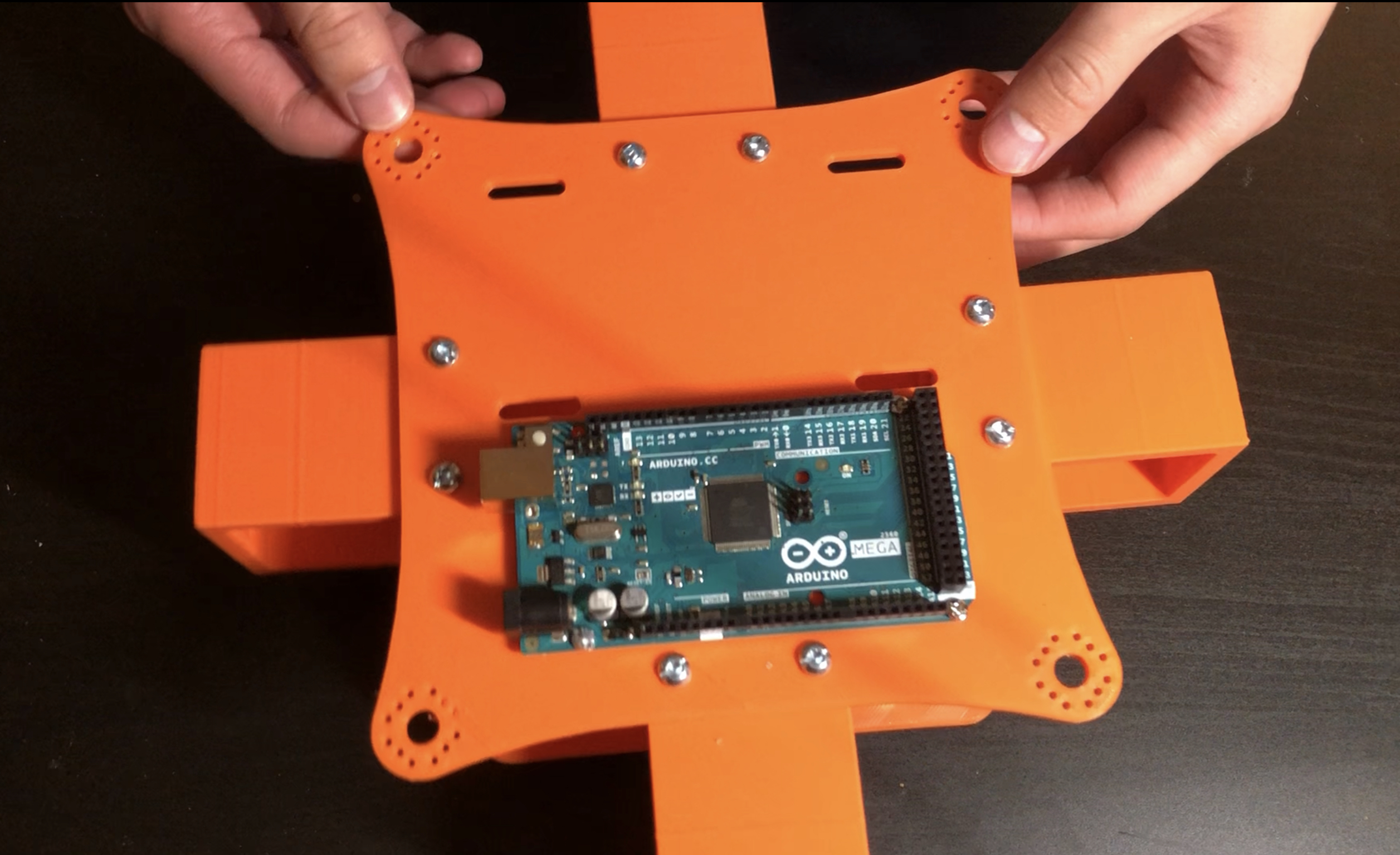
The last section of the script exports the joint angles to a CSV file, which can then be copied into the code that runs on the Arduino. Some conversion is required to transform the joint angles from the global reference frame to the local servo reference frame.


    function save_qs_to_file(qs)
        % Convert from rad to deg
        qs = rad2deg(qs);

        % Copy initial angles to the beginning
        q_init = qs(end,:);
        qs = [q_init; qs];

        % Convert to servo angle reference frame
        % Set all angles to zero-referenced
        qs = qs - qs(1,:);
        % Reverse directions of joint angles as needed
        qs(:,1) = qs(:,1)*-1;
        qs(:,4) = qs(:,4)*-1;
        qs(:,7) = qs(:,7)*-1;
        qs(:,10) = qs(:,10)*-1;

        % Add joint angle offsets
        qs(:,1) = qs(:,1)+90;
        qs(:,2) = qs(:,2)+90;
        qs(:,3) = qs(:,3)+225+q_init(3);
        qs(:,4) = qs(:,4)+90;
        qs(:,5) = qs(:,5)+90;
        qs(:,6) = qs(:,6)+225+q_init(6);
        qs(:,7) = qs(:,7)+90;
        qs(:,8) = qs(:,8)+90;
        qs(:,9) = qs(:,9)+225+q_init(9);
        qs(:,10) = qs(:,10)+90;
        qs(:,11) = qs(:,11)+90;
        qs(:,12) = qs(:,12)+225+q_init(12);

        % Round to nearest integer
        qs = round(qs);
        writematrix(qs, 'temp.csv');
    end
                

The main code that runs on the Arduino is located here, 
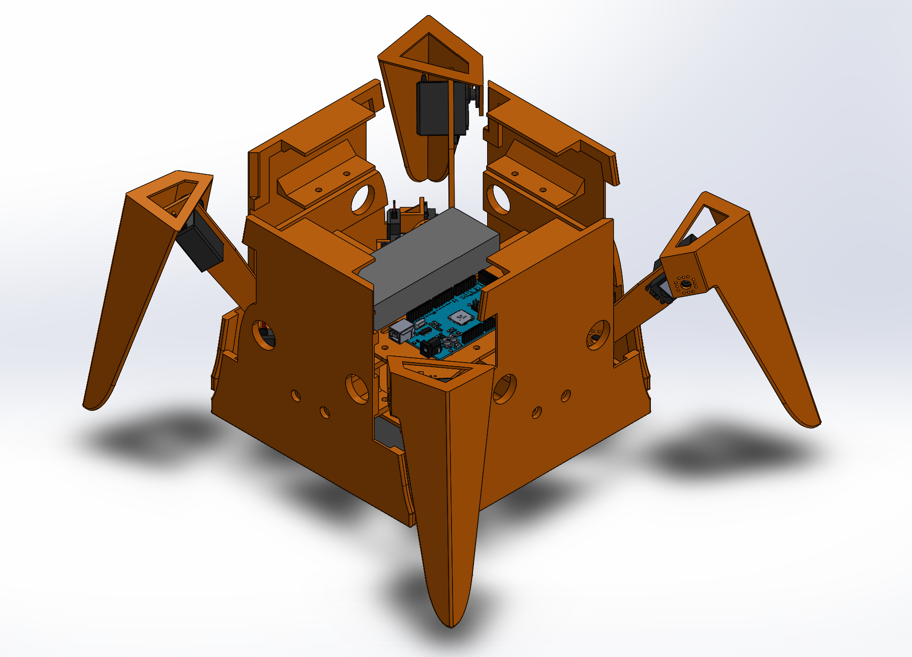
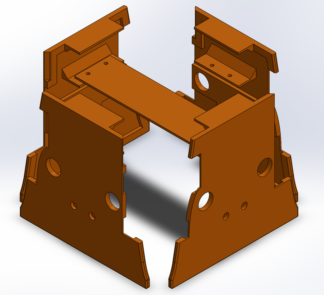
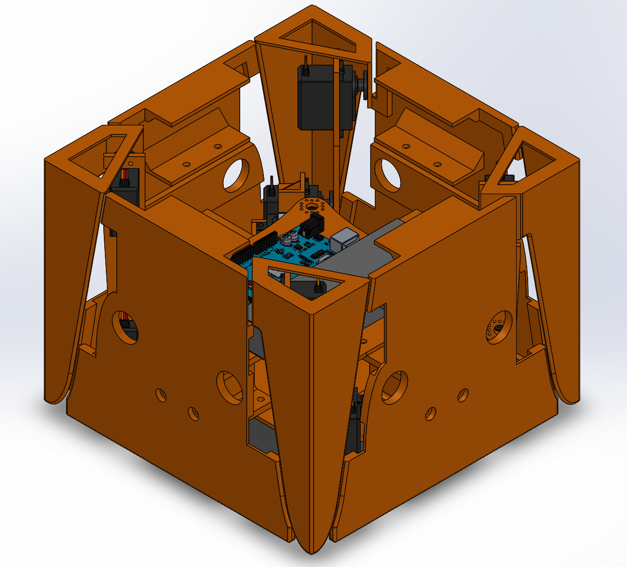
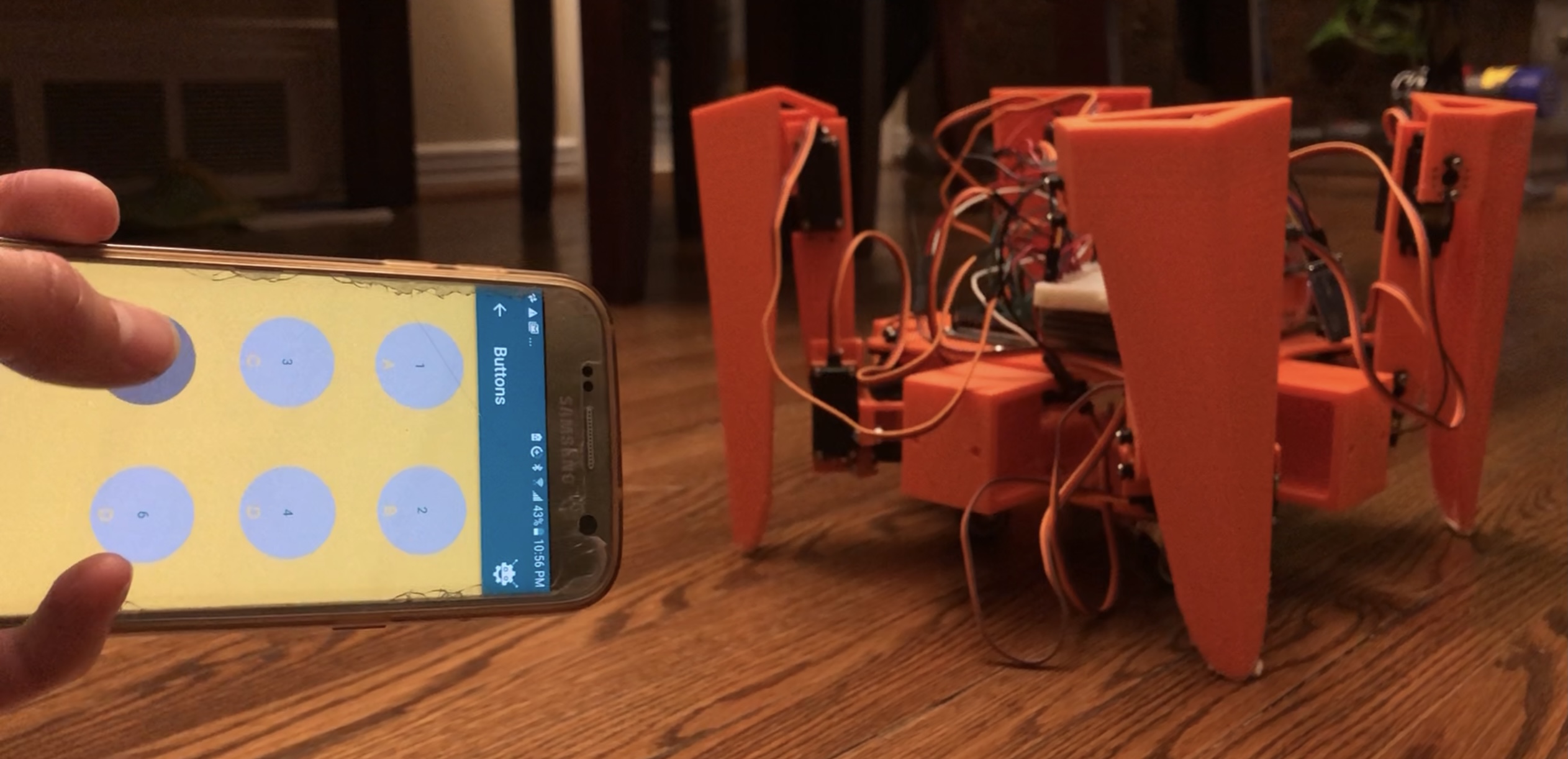
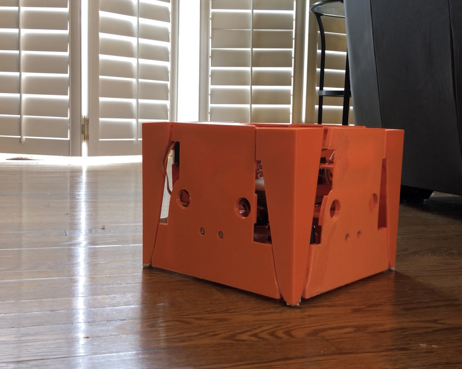
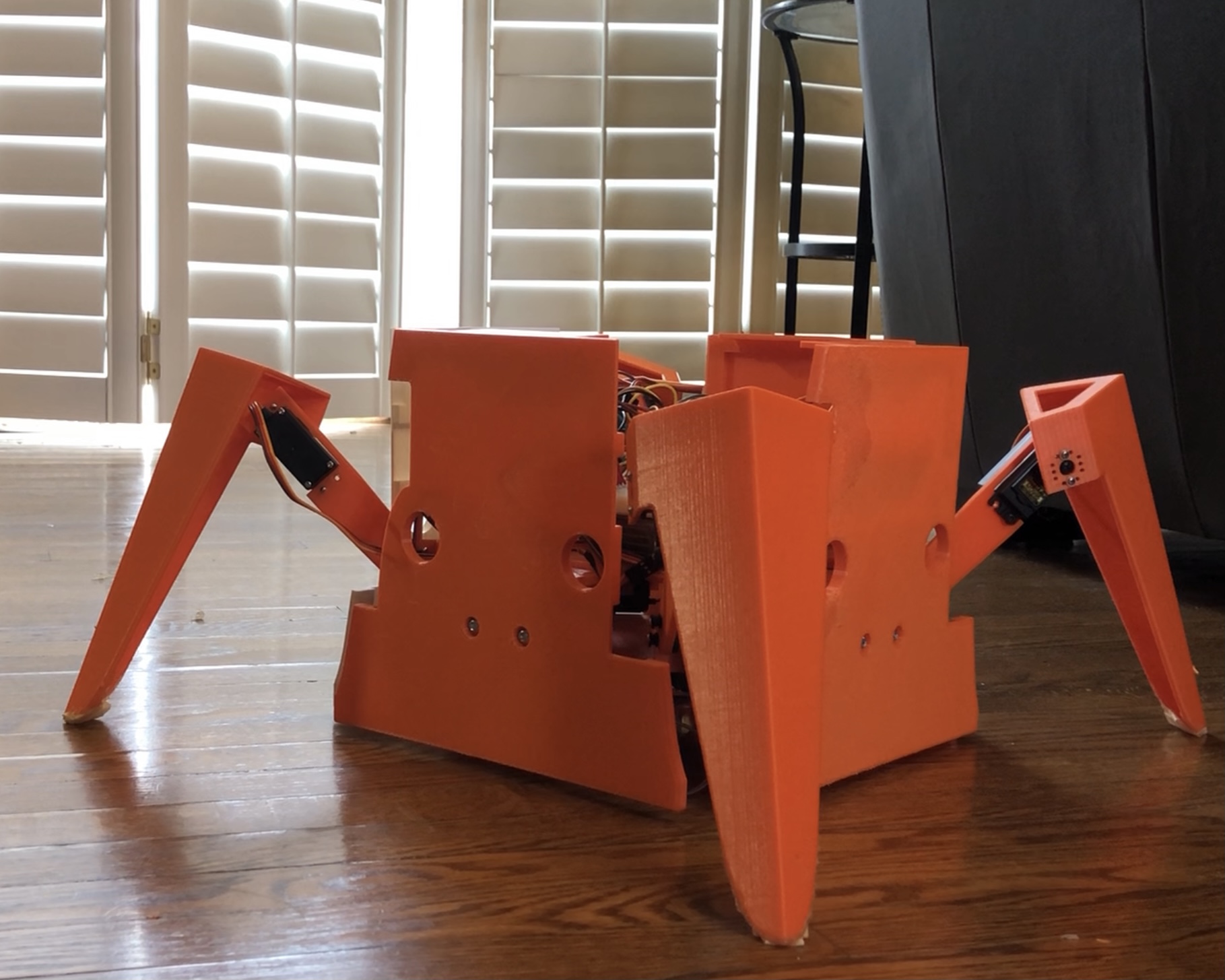
and is fairly straightforward. The program initializes all servo angles 
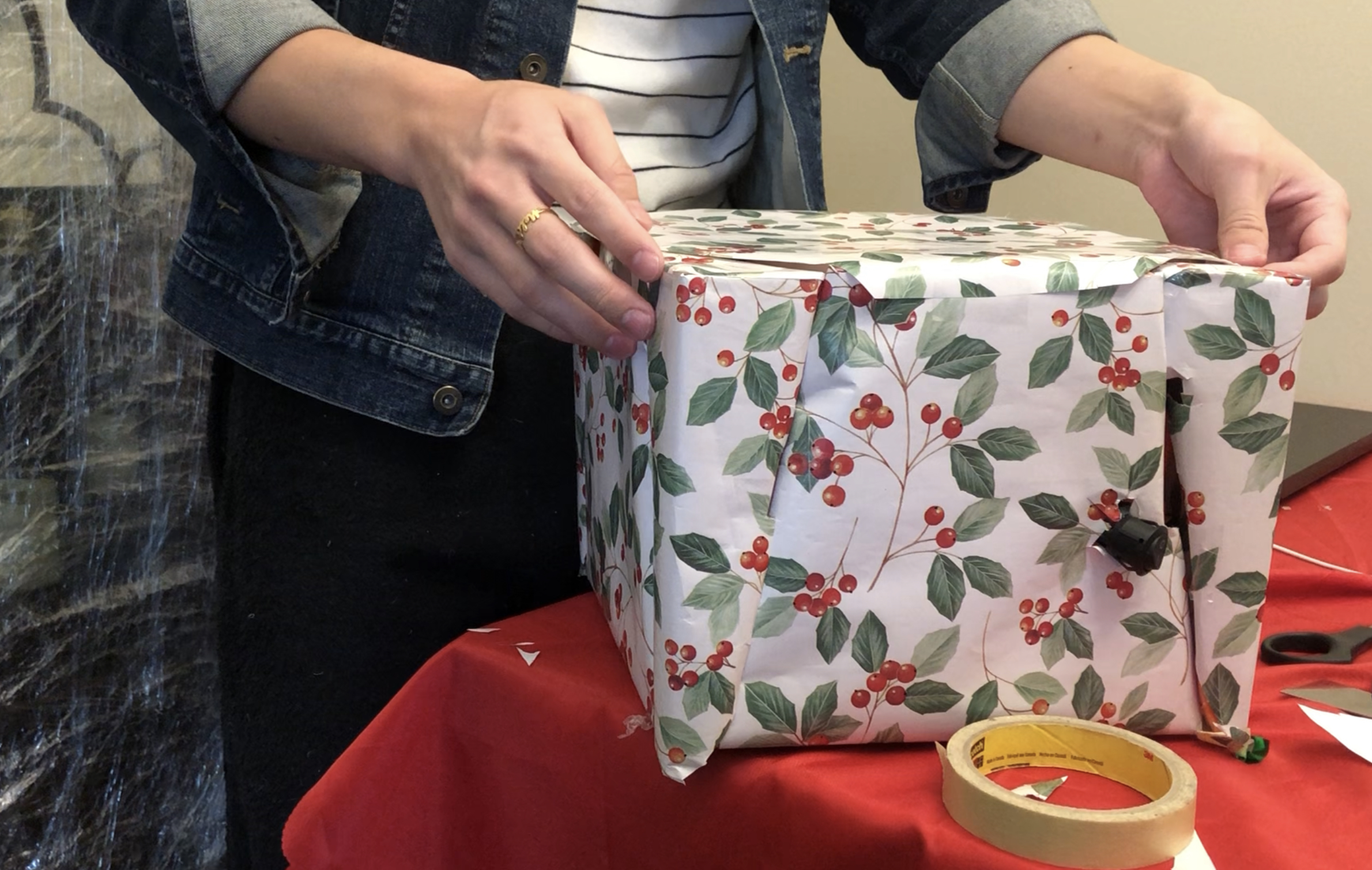
to their closed positions, which causes the legs to retract into a box. 
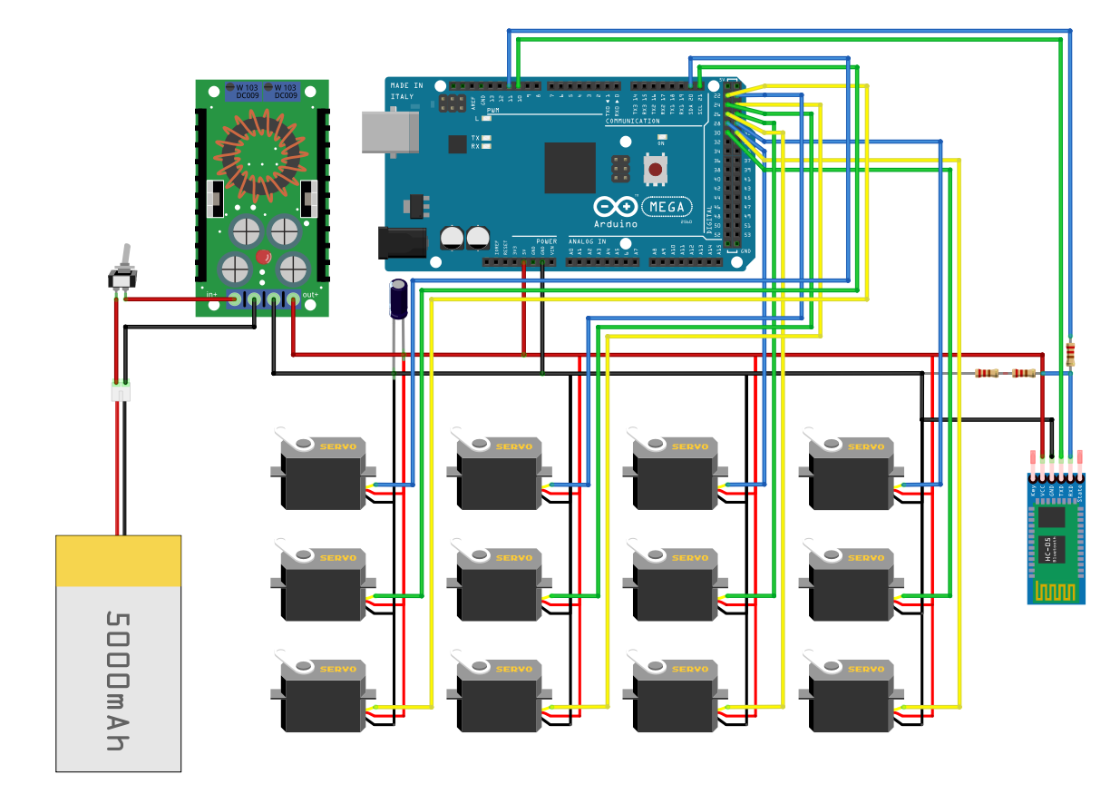
The main function then continuously listens for a message over Bluetooth, which is triggered by a button press from my phone. I'm using an app called Arduino Bluetooth Control which I found for free on the Play Store to communicate with my HC-05 device, though there are plenty of other apps out there that can serve the same purpose.

This allows me to configure different buttons to send specific messages to the Arduino over Bluetooth, which get decoded to perform certain actions. These actions include opening/closing the legs, moving forward/backward and rotating clockwise/counter-clockwise.


    void loop() {
        while (!HC05.available()) {
            delay(5);
        }
        int button_cmd = HC05.read()-'0';
        Serial.println(button_cmd);
        switch (button_cmd) {
            case BTN_OPEN_LEGS: {
                if (!legs_open) {
                    open_legs();
                    legs_open = true;
                }
                break;
            }
            case BTN_CLOSE_LEGS: {
                if (legs_open) {
                    close_legs();
                    legs_open = false;
                }
                break;
            }
            case BTN_MOVE_FORWARD: {
                if (legs_open) {
                    actuate_servos(servo_util::MOVE_FORWARD_ANGLES);
                }
                break;
            }
            case BTN_MOVE_BACKWARD: {
                if (legs_open) {
                    actuate_servos(servo_util::MOVE_BACKWARD_ANGLES);
                }
                break;
            }
            case BTN_ROTATE_CW: {
                if (legs_open) {
                    actuate_servos(servo_util::ROTATE_CW_ANGLES);
                }
                break;
            }
            case BTN_ROTATE_CCW: {
                if (legs_open) {
                    actuate_servos(servo_util::ROTATE_CCW_ANGLES);
                }
                break;
            }
            default: {
                Serial.println("Unrecognized button press");
                break;
            }
        }

        // Clear serial buffer
        while (HC05.available()) {
            HC05.read();
        }
    }
                

The servo_util file defines a number of constants used by the main program, such as the hard-coded servo angles for each walking motion which were computed via simulation, as well as the pulse ranges for each servo determined from calibration.

Assembly

The following list contains some links to the specific parts I used during this project. Generally speaking, the parts can be acquired from different vendors and can be substituted for different models as well depending on price, availability and other factors.

All robot parts in the CAD Model are 3D printed from PLA plastic. I'm using a Creality Ender 3 Pro to print the parts, and Ultimaker Cura as the slicing software.

First, the robot base is assembled. For the most part I use 8-32 x 1/2 machine screws and nuts to fasten the components of the robot together. This size fits with the caster wheels I have purchased, so most of the robot parts are designed for this size. When fastening the casters to the base plate, it is important to verify that the head of the bolt does not interfere with the range of motion of the caster wheel.

The modified I-beams can then be fastened to the base plate, followed by the top plate mounted on top of the I-beams. The top plate contains mounting holes for the Arduino Mega, as well as slots for optionally securing the battery with zip ties beside the Arduino.

The breadboard and DC-DC converter are placed on top of the battery, with a 3D-printed bracket holding the DC-DC converter in place.

The robot legs can be assembled next. Custom brackets are used join two MG995 servo motors at the hip joint. This connects the servos at 90 degree angles to each other to provide rotation about two perpendicular axes. The brackets are joined using the same 8-32 x 1/2 machine screws, while the servos are fastened to the brackets using size 6 x 3/8 screws. This size is small enough to pass through the mouting holes of the servo and can thread directly into the plastic of the bracket.

The thigh component can then be fastened to a third servo at the knee joint, and the calf component connects to the servo horn of this third servo. I'm using round servo horns for this project.

Before mounting the horns to the servos, the servos need to be calibrated (see Servo Calibration section). It is also important to set the servo angle to some known value to ensure that I'm mounting the thigh and calf components in the correct orientation. This can be accomplished by mounting each component in its closed-box position (as in the CAD model) after setting each servo to its initial angle position. By default, the output gear of the servo rotates counter-clockwise for an increasing angle command. For example, this means that the servo rotating the calf should be set to 45 degrees in its closed-box position (when the calf is parallel to the thigh). This ensures that as the knee servo rotates counter-clockwise from 45 to 135 degrees, the calf will extend from its closed position to fully opened. Similarly, the servo rotating the thigh should be set to 135 degrees in its closed-box position, so that when rotating clockwise from 135 to 45 degrees, the thigh extends from its closed position to fully opened.

The thigh can then be mounted to the corresponding servo horn at the hip joint, while the other servo horn at the hip joint is mounted to the top plate, which rotates the entire leg with respect to the robot base. This process can be repeated for all four legs.

At this point, it is probably a good idea to test movement of each leg. There are many ways to do this, but personally I would sweep each servo from 45 to 135 degrees and verify that the range of motion for each joint looks correct. This is a good way to test all components are wired correctly according to the schematic in the Electrical Design section, and also check if all parts and servos are mounted in the appropriate orientation. I can also run all 12 servos at once to check if the battery can handle the power draw. It is best to perform these tests before attaching the walls to the robot, to avoid any collisions between the legs and walls.

If all goes well, then next the Bluetooth module can be wired into the system and the code can be tested. To do this, I'll upload the main script to the Arduino Mega and connect to the HC-05 with my Bluetooth app. I would first test if opening/closing the legs of the robot works, and then test the walking motions afterward. In my case, I find that there is not enough friction between the robot's plastic feet and the floor, and as a result the robot could not move itself even though it is generating the correct walking patterns. I manage to get around this by sticking double-sided tape onto the robot's feet to create more friction, but there are probably other ways to resolve this by using other materials for the feet such as rubber.

Once satisfied with the robot's movement, the walls of the gift box can be mounted to the exterior flat surface of the modified I-beams. It is worth testing the walking motions again after mounting the walls to ensure there is no interference. There are also holes in the walls which can be used to provide access to a power switch, or to route a cable if reprogramming the Arduino is needed.

A small platform can be optionally fastened to the walls inside the box, which I'm using to hold gifts inside the robot.

The final step is to wrap up the robot using some festive gift wrapping paper. I'm also poking a small hole in the back for the power switch... but I'll be sure to conceal this side of the robot from other people.

And there you have it! The walking Christmas present robot is complete, and is ready to deliver gifts and surprises to family and friends :)

Contact

I hope you enjoyed this project tutorial! If you'd like to support my work, please consider subscribing to my YouTube channel. Any questions/comments can be directed to my email address. Thanks for reading!

All code/resources used in this project can be found in the GitHub repository and are provided under the MIT License with Commons Clause License Condition. These resources are free to use for non-commercial/not-for-profit purposes. The full license may be viewed here.

Copyright © 2021 Russell Wong